
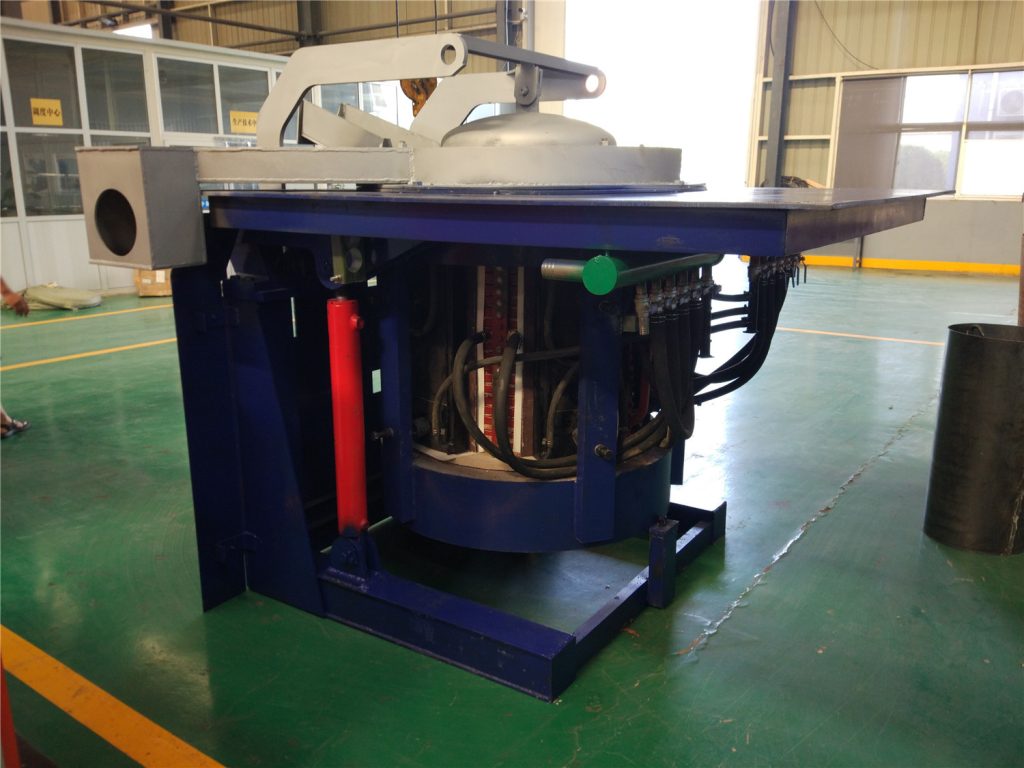
In modern metallurgy and foundry operations, the melting section represents up to 40% to 60% of total plant energy consumption. Traditional combustion-based equipment—such as gas-fired reverberatory furnaces—presents inherent operational limitations, including excessive thermal radiation, uncontrolled metal burn-off, and high maintenance frequency.
Understanding how an induction furnace works is essential for foundry managers, metallurgists, and procurement teams looking to optimize operational expenditure (OPEX) and improve molten metal quality.
1. Operating Principle: How Does an Induction Furnace Work?
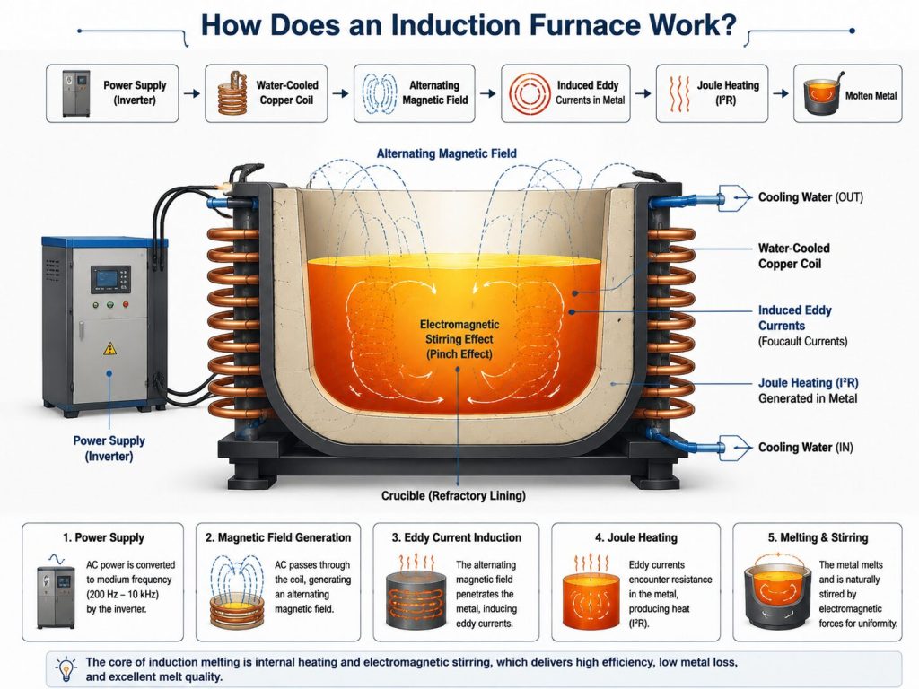
Unlike fossil-fuel furnaces that rely on thermal radiation or conduction from an external flame, an induction furnace generates thermal energy internally within the metal charge itself.
[ Power Supply / Inverter ] ➔ [ Water-Cooled Copper Coil ] ➔ [ Alternating Magnetic Field ] ➔ [ Induced Eddy Currents in Metal ] ➔ [ Joule Heating (I²R) ]
The Electromagnetic Physics
- Alternating Current & Magnetic Field: A medium-frequency alternating current (typically ranging from 200 Hz to 10 kHz, depending on capacity and alloy) passes through a water-cooled copper coil surrounding the furnace crucible.
- Eddy Current Generation: The high-frequency magnetic field penetrates the metallic charge, inducing intense eddy currents (Foucault currents) within the metal.
- Joule Heating ($I^2R$): Due to the electrical resistance of the metal, these induced currents generate rapid Joule heating, transforming solid scrap or ingots into a homogeneous liquid state without direct physical contact with a heating element.
Electromagnetic Stirring Effect
As magnetic field forces interact with the induced currents, a natural electromagnetic stirring action (pinch effect) occurs within the melt pool. This ensures uniform chemical composition, precise alloy homogenization, and consistent temperature distribution throughout the heat—critical factors for high-precision casting.
2. Technical Comparison: Induction vs. Combustion vs. Crucible Furnaces
Selecting the wrong melting technology directly impacts yield rates, energy bills, and refractory lifespan. Below is an engineering comparison across key operational parameters:
| Operational Parameter | Medium-Frequency Induction Furnace | Gas-Fired Reverberatory Furnace | Crucible Melting Furnace |
| Primary Energy Source | Electricity | Natural Gas / LPG | Electricity or Gas |
| Thermal Efficiency | 65% - 78% | 25% - 35% | 30% - 45% |
| Metal Loss (Oxidation) | < 0.8% - 1.2% | 3.0% - 5.0% | 1.5% - 2.5% |
| Temperature Control | Precision within $\pm 3^\circ\text{C}$ | Manual / High variance | Moderate precision |
| Melt Rate / Tonnage | High (0.5 to 50+ Tons) | High (Bulk melting) | Low to Medium (< 1 Ton) |
| Alloy Flexibility | Excellent (Easy grade changes) | Poor (Cross-contamination) | Good for small batches |
3. Real-World Foundry Pain Points Addressed by Induction Melting
Pain Point 1: Severe Metal Losses (Burn-Off)
In gas furnaces, direct exposure of the metal bath to high-temperature oxygen-rich burner flames results in severe surface oxidation. For aluminum, copper, and specialized alloy steel, oxidation losses can exceed 3% to 5% of total input material.
- The Induction Solution: Internal Joule heating eliminates flame contact. Oxidation rates drop to below 1%, saving thousands of dollars monthly in raw scrap costs.
Pain Point 2: High Energy Consumption and Thermal Footprint
Combustion gases carry away more than 60% of the input heat through the stack.
- The Induction Solution: With electrical-to-thermal conversion efficiencies exceeding 70%, power consumption for steel melting typically averages 500 – 580 kWh/ton, while aluminum melting operates around 480 – 550 kWh/ton.
Pain Point 3: Inconsistent Melt Chemistry and Inclusion Defects
Stagnant melt pools require manual rabbling, leading to temperature stratification and localized overheating, which degrades casting mechanical properties.
- The Induction Solution: Natural electromagnetic stirring continually mixes the alloying elements (e.g., Si, Mn, Cr), preventing element segregation and oxide inclusions.
4. Equipment Selection Framework & Application Scenarios
Choosing an induction melting furnace is not merely about selecting tonnage; it requires balancing electrical infrastructure, crucible material, and production workflow.
Equipment Selection Framework

Selecting the wrong induction melting furnace leads to high energy waste or frequent refractory failure. Engineering teams must evaluate three core determinants before finalizing equipment specifications:

Metallurgy Type (Ferrous vs. Non-Ferrous): Directs the choice of operating frequency, coil geometry, and refractory lining.

Duty Cycle Needs (Continuous vs. Batch): Determines whether a single-body furnace or a dual-track duplex system is required.

Power Infrastructure (kVA & Harmonics): Dictates transformer capacity and power supply modules needed.
Scenario A: Precision Investment Casting & Alloy Steel
- Recommended Setup: Steel-shell medium-frequency induction furnace with IGBT solid-state power supply and neutral (spinel/alumina) lining.
- Why: Requires precise superheating temperatures, rapid melting cycles, and zero chemical contamination between heat runs.
Scenario B: Aluminum Die-Casting & Scrap Recovery
- Recommended Setup: Coreless induction furnace or heavy-duty crucible furnace with specialized ceramic lining.
- Why: Crucible furnaces suit small-batch, multi-alloy non-ferrous operations due to low initial capital expenditure (CAPEX). However, continuous medium-to-large aluminum casting operations favor medium-frequency induction for lower melt-loss ratios.
Scenario C: Ductile Iron & Gray Iron Foundries
- Recommended Setup: Dual-track/duplex induction melting system (one power supply feeding two furnace bodies for simultaneous melting and holding).
- Why: Guarantees constant liquid metal availability for automatic molding lines without power surges.
5. Cost Factors, Maintenance & Avoiding Cheap Equipment Pitfalls
Key Operational Cost Drivers (OPEX Breakdown)
- Electrical Power: 60% – 70% of ongoing melting costs.
- Refractory Lining Replacement: 10% – 15% (Lining wear rate depends directly on slag chemistry and thermal shock).
- Cooling Water System: 5% – 8% (Chiller and closed-loop heat exchanger pump power).
Warning: The Hidden Trap of Low-Cost Induction Furnaces
Purchasing an underpriced induction furnace often leads to severe long-term financial drain. Low-cost manufacturers cut corners on critical components:
- Inferior Thyristor/SCR or Low-Grade Capacitors: Cause frequent harmonic distortion, high transformer losses, and unstable inverter switching.
- Thin Copper Tubing in Induction Coils: Increases internal coil resistance, leading to energy waste and higher risk of water-leak burn-through.
- Substandard Refractory Materials: Lead to rapid lining erosion, increasing the risk of molten metal breakout.
A single unplanned downtime event caused by coil breakdown or power supply failure can result in lost production costs far exceeding the initial price difference of a premium furnace.
6. Preventative Maintenance & Operational Best Practices
To ensure maximum uptime and prolong furnace campaign life:
- Daily Water Circuit Monitoring: Inspect water temperature, pressure, and conductivity in the closed-loop cooling system to prevent scale buildup inside the copper coil.
- Refractory Lining Wear Tracking: Measure crucible wall thickness daily using depth gauges or automated lining wear monitors to prevent metal penetration.
- Charge Material Quality Control: Ensure scrap is dry and free of oil or closed containers prior to charging to eliminate dangerous explosion hazards and excessive slag buildup.
Technical Support & Custom Furnace Engineering
Selecting the correct induction furnace requires an in-depth evaluation of your plant's power grid capacity, production schedule, raw material geometry, and target metallurgy.
Planning a new melting line or upgrading an inefficient gas furnace?
Contact our metallurgical engineering team today with your target daily output (tons/day), alloy specifications, and facility power limits to receive a customized equipment configuration and payback analysis.